Slabbing Frame
Slabbing Frame
Described by Peter Herbert, Warren Harris and Keith Jeeves
Holding a burl or a rough piece of wood while trimming with a chainsaw can be difficult and potentially dangerous.
The slabbing frame described in the drawings and shown in the photographs allows the wood and chainsaw to be securely held so if anything does go wrong, the risk of damage or injury is greatly reduced.
As the chainsaw is guided through the cut, the resulting face is likely to be flatter and more usable than if free-sawn.
To use the frame;
- Position and securely tighten the bottom wood holder locking screw.
- Place the wood to be sawn onto the bottom prongs.
- Bring the top wood holder down onto the wood and firmly drive the top and bottom prongs into the wood by striking the top wood holder with a hammer.
- Securely tighten the top wood holder locking screw.
- Mount the chainsaw on the support bar by means of the stud passing through a hole drilled in the chain bar and securely tighten the nuts and locking nut. The chain bar must be firmly locked onto the support bar, rotation of the chainsaw through the cut is acheived by rotation of the support bar in the mounting tube.
- Locate the support bar mounting tube at an appropriate height to begin the cut.
- Position the support bar at the appropriate cutting position, place the collars against the support bar mounting tube and securely tighten the locking screws.
- Start the chainsaw and begin the cut.
- Adjust the height of the support bar mounting tube as the cut progresses as required.
It is not clear who actually designed the frame. It was first seen being used by Darrel Smith from Western, modified by Bankstown (I think) and further modified by Southern Highlands.
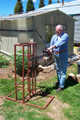
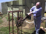
The following photographs show the slabbing frame in use, click on an image for a larger view.
Download a pdf file (8.4kb) of the manufacturing drawings.
Note that the frame shown in the photographs has been modified to allow easy dismantling for transport.
Sockets have been fitted to the base allowing the upright section of the frame to be removed. Bracing has been fitted to the upright frame to provide rigidity. If the frame is fully welded, the bracing would not be required.
The drawings are provided for guidance only, there is a great deal of flexibility to modify the design to suit particular requirements and materials available.
Back to the Articles page